The Three Tube Mini Boat Anchor Experience
or , “Thank goodness hams
retired this stuff !”
Jeff VE1ZAC
Some “Months”
back, I thought it would be fun to dig out some junk box parts and show my son how
“Easy” it would be to knock together a really simple CW tube transmitter. I admit, I was taken
by the “WD8DAS Two-Tube Tuna Tin Transmitter” that was published in QST. Zac
and I decided it should be similar and crystal controlled.
But
then… I started to
think, why not jazz this thing up a little ? Why not indeed ! A couple of bands would be good. QRP action, let’s
do 80 and 40 M . What the heck toss
in 30M and 20M too, as it is only a tank circuit we are talking about. Band switching, sure, easy.
More features ? You bet ! Power supply on the
chassis. Yup. I have lots of 5763’s, so why not
parallel up the PA stage for more power ? Sure thing. A “Rubber” control. Spot switch. A meter to see PA mA. A T/R relay. An isolated cathode keying circuit for safety. Maybe a
regulated B+ for the oscillator. A semi break in
control. Oooooh… I even found a couple of unused vernier drives. A receiver antenna
output. Yes, yes , YES !
(……………You see, this how engineers get themselves in trouble. Feature
creep.)
Well, with the
exception of the crystals, the junk box did indeed produce all the gubbins needed to start. And start we did.
Problem number
1 was innocent enough. The
only thing even close to a chassis I had around was a heavy steel box. It was
just too heavy to be considered simple chassis work, so it quickly became a machine shop project.
I needed the
vertical mill to whack holes in the beast. I lost Zac about this point. No
problem, I thought, I will just get this chassis done and painted and then Zac
and I could recreate that mythical Heathkit
experience as father and son spend pleasant hours soldering parts into the
chassis and operate the thing on the air.
( I really should have sobered up at this point
and bailed out, in hindsight)
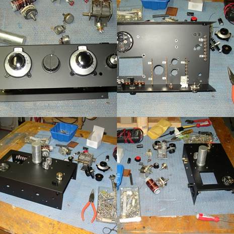
Chassis done,
parts rounded up, everything fitted out. Construction phase pictures.
So
far, so good. I managed
to keep Zac interested for about 20 minutes. He normally likes soldering parts
to circuit boards, but this was far more difficult and demanding. Lost Zac for
the second time at this point and I gamely soldered on. I finally got the basic
stuff together. I started out with the 6C4 oscillator and would use the 5763’s
as a parallel PA stage. (I calculated the tank impedance to match two 5763’s in
parallel.)
Problem number
2: I didn’t have the right power transformer. I
have lots of old salvaged power transformers but they all produced way too much
voltage on the secondary. I wound up spending oodles of hours screwing around with this issue, trying up to half a dozen different arrangements to get to
the needed 250 V DC B+, 6 VAC for the
heaters and 12 V for that non tube feature list that I had decided to throw in
! The dagnabbed ^&%$^%#%$#%$#%^$$ power
transformer was finally working. Time spent so far: 17 hours. Yikes !
OK, it’s all
together. NOW I can get to the rush of operating my new tube rig
! Ummm,
well, not quite yet.
Problem number
3 rears it’s
head. The 6C4 works OK but droops like crazy. Man, I turned a receiver on to
listen to the oscillator while keying the unit. I couldn’t put that on the air.
It was awful. It might be something you could use to extract confessions
, but it sure wasn’t going to contribute to a QSO. Now I decided that
what I really needed was a high voltage regulator in the thing. I have lots of
tube regulators but it would involve drilling another hole in that hateful
nuclear bomb proof chassis. I decided to “Cheat” and slip a power NMOS fet shunt regulator inside where
nobody could see it. After all, I did use a couple of NMOS fets
to do the cathode keying to keep lethal voltages off the key contacts. Nobody
would ever know. Right ? Another 12 hours rolls by.
New total : 29 hours.
Is the rig working
yet ? No.
Problem
number 4 hoves over the horizon. I can’t get more than about 12 V RMS
across the 50 ohm dummy load with the bleeping thing. This equates to about 3
watts RMS out. Wow, after all that, and it weighs about 15 lbs at this point. 5 lbs. per watt. A marvel of modern
materials and methods. At this point, I pretty much abandon my dream of
the cute little two tube rig, and realize I have entered the world of BA’s. ( Boat anchors, if you haven’t heard that term before)
I decide to get
this thing on the air and manage to coax Gary VE1RGB and Dick VE1AI into an 80
M QSO. That goes OK. All the way across town too !
Wow.
Intermission ( of 3 months)
Just to prove that
as you get older, your memory fails more often, I decided this week to have
another go at my albatross, er, I mean tube project.
Digging out my tube references and working through the load lines for the
5763’s, I decide that my problem may be the 6C4. It’s not up to the drive job
needed to drive the two 5763’s. What I
need is a beefier oscillator. I decided to use another 5763. That entails a
rethink of the whole thing. The original circuit coupled the oscillator to the PA
with no tank or filter. That isn’t really good practice, so I decide to add
another small tuned peaking filter for the oscillator.
Problem number
5: there is no more room
under this pig for another coil and variable capacitor. Only one
thing left to do… add a carbuncle on top and yet another knob to twiddle with
on the front panel. It’s getting heavier !
While I am at it,
I try and remove some of the now surplus junk and just generally bad ideas. The
verniers were a complete waste of time. I got rid of
one. The “Stealth HV regulator” was no longer needed, so out it went.
The new oscillator
works fine. And, my new output power is : slightly
better than before. I might be able to claim a whopping 6 or 7 watts on some
bands. A pile up buster it isn’t.
No more changes
for now. It’s time to work a few brave souls and put some operating time on
this thing.
Time on this last
phase: 12 hours. New total 41 hours. Almost a work week. Was it worth it ? I will have to think about that. Total father
and son Heathkit time: about 60 minutes.
Another change was
in order. I noticed during operation that the little RF chokes I was using for
the plate circuits were getting VERY warm. How do I know this
? Smoke and plastic were being
ejected from the things in a long key down test. Oooops. I found an old
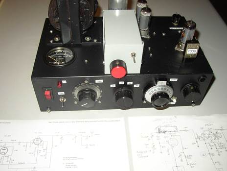
ceramic coil form and wound a proper choke with some heavier wire. Here is a picture of the guts: (which I am
somewhat reluctant to show)
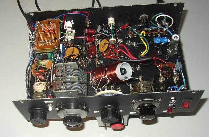
It’s a bit of a
mess. This is the problem with a live “breadboard” project that you keep
changing. They all turn into a mess. You can see the new PA plate choke, the
green wire wound on the ceramic form on the rear. Also you can see the end of a
piece of ferrite bar I stuck in the tank coil to provide a little “Fine tuning”
to the coil. Lower left corner is the oscillator, above that is the relay and
cathode keying and break in circuit. To the right of that are the PA’s, then
the transformer. Back to the lower right corner is the PA mA meter, and then
the tank consisting of the two capacitors and switched coil assembly.
Operating
My Autek inline power meter tells me this thing delivers a
solid 4 to 5 watts on 80,40 and 30M. 20M is less , but the oscillator isn’t real stable on 20 anyway, so
I probably will just give up on that band. The other three are operating OK.
The freq is a bit unstable but I have had QSO’s on the bottom three bands on the QRP part of
the bands and nobody screamed at me. It’s useable. It sure makes you realize
how spoiled we are with our new transceivers though.
Here is my crystal
stash. I have two “Rocks” for each band and I can “Rubber” the frequency a
little on either side of these. 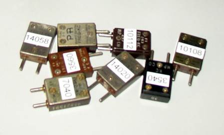
If anybody wants to
try a QSO while I use this thing, send an email and we will set up a sked.
I tried the rig
out this afternoon on 40 and 30. First contact on 40 was with a fellow in NY
who said my 4 watts was a very good signal on the band and we gave each other a
599. The 30 M contact was a CQ with 3 watts, and who comes back to me but a 13 year old ham in
Postscript
If
you decide to have a go at a “glowbug” project like
this, be advised that most of these tube circuits have need of a B+ power
supply of over 150 VDC and currents sufficient to kill you, if you elect to do
something foolish. If you are unfamiliar with higher voltage power supplies and
circuitry like this, get a little coaching from somebody who knows what they
are doing first. And, of course, be careful with kids and pets hanging around
while you have stuff exposed. Begillions of people
have worked on stuff like this, so don’t get all freaked out about high
voltages, just put your high voltage safety hat on !
Addendum
It’s fun to
re-read some of these stories and laugh at the decisions one makes during the
“History” of a project. Remember the removal of the useless vernier
and the HV power supply ? They’re back ! I had another go at fine tuning the rig and
have it working on all 4 bands now. It can do 7 or 8 watts on 80 and 40 and 5
watts on 30 and 20M now. The tuning is kind of fussy, so the verniers are useful after all. Plus, one can make a little
chart of the settings for rapid setup. The droopy oscillator was finally solved
by leaving the oscillator running all the time. Problem with that is the
receiver staying locked onto that signal even while you are trying to listen. I
solved that problem by turning the oscillator on with the T/R relay and leaving
it on during a burst of dits and dahs. It goes off
during the listen periods. It’s a bit unusual to operate with this but it works
fine and the operator on the other end will be appreciative of a steadier tone
on their receiver. ( I hope).
Lessons learned
( or re-discovered)
It’s easier to
build a simple transmitter from solid state devices, and it will probably work
better.
Tube rigs are big
and heavy!
They do indeed
glow and get warm. ( A nice wintertime feature)
Full or semi break
in with a simple tube rig is rather problematic. It would be a lot simpler to
use a manual T/R switch, which would also take care of all the other issues
like droop and stability.
Multi band
features add a
One does indeed
feel a connection with the earlier days of radio when you make an attempt to
get a tube circuit running.
Happy tubing !