More on Using an Arduino
with IC7700 and MFJ998 tuner
Jeff
VE1ZAC May 14,
2011
My
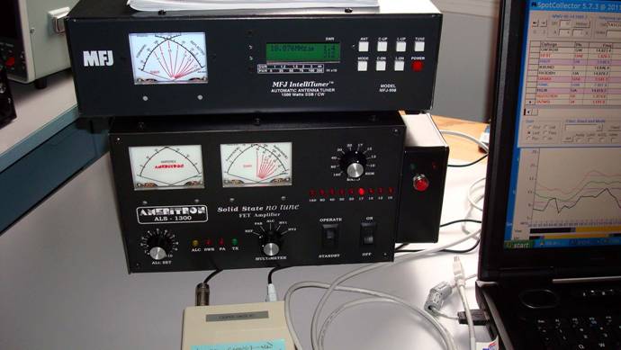
previous write up described how I solved the missing remote tuner connection to
an IC7700 by using an Arduino single board processor to act as a go between on
the Icom CIV line and the tuner’s AH-3 style connection.
I have
since refined the code a little and discovered some important ancillary
features that need to be considered.
Hardware
items:
I
replaced the push button from the previous article with a much nicer one that
requires very little pressure to activate. Note, in the code, that the button I
used is normally closed. If you were using a normally open one, you would need
to change a few things.
I have
also discovered that the “Tune” button on the tuner itself will do some things
with the AH-3 control lines that could have been used to initiate the tune
cycle, if I had realized it before starting. The push button I added could have
been skipped. On the other hand using a push button with an Arduino is about as
simple as unwrapping the Arduino when you receive it.
Some
Icom things:
The CIV
line is prone to collisions of data streams when more than one device is using
it. In my case, I want this thing to work at the same time that DXLab Commander is controlling the transceiver. It is just
about impossible to avoid collisions or conflicting commands when Commander is
running, as it assumes it is the master of the CIV line. I noticed there were
some funny goings on when Commander was in “Continuous Interrogate” mode (found
in the config window of Commander). When it’s off, there are no problems. When
it’s on with a short command interval there are occasional glitches. Dave Bernstein described this to me as
‘Playing Russian roulette with a loaded gun, and occasionally (some command)
will blow up’. Great description!
Further,
continuous interrogation provides for the cursor in the bandpsread window
following the transceiver frequency… something I am kind of addicted too. I did
find I could leave continuous interrogation on if I set the command interval
fairly long to 500 mS. This is a compromise, but
allows very reliable remote tuner operation. Also, the “Transceive” option in
the Icom setup menu must be off. I have
delays tweaked in the code to work with a CIV speed of 19200 baud.
I am
using the Icom’s RS232 port as a CIV port for the
computer, and the CIV jack on the rear panel for the Arduino/tuner line.
The
code and operation was laboriously tested with these parameters in place by
initiating a tune 100 times with the push button, about half with transceiver
with split VFO’s, and half without. No
glitches, so this is a good setup.
There is another potential refinement I could engage in, and probably will try at some point. Right now I determine if the transceiver is split by polling it myself. This likely increases the probability of collisions. If I was always going to use this with Commander, I could skip the polling and just listen for split data, as Commander does that task now. Then I would assume the transceiver is not split, unless I tapped into a 'split' data stream between the transceiver and Commander. The downside of this method is that Commander would have to be running, where as my present system works with or without.
If you
want to try this or adopt this code to work with other CIV functions and want
the file drop me a line and I will send it along.
Latest
software revisions:
// NOTE.. Commander could interfere with some of the
split vfo directives. Caveat Emptor
//this software runs perfectly without Commander doing
continuous interrogation.
// checking with Dave Bernstein for a Commander
solution
//This is the E1 control version
// Works OK with Commander , and 500 ms
//command interval, continuous interrogate on
// *** Note, this is for IC7700 where Commander uses
RS232
//port and Arduino uses CIV line *****
// 19200 baud interfaces, important
//all built in delays are important
//the AH-4 tuner function for Icom
CI-V and MFJ 998 control
//commands work with Icom
interface enabled in 998 tuner
//and Icom CI-V line with
Arduino processor
//reads key line from tuner
//controls start line and radio Tx
and Rx
//
// define the pins we need for interfacing
//LED is to show STARTTUNE running
// Use a delay when turning split on and off before
proceeding as rig
//is slow to respond
// this one for NC tune push button
#define TUNEBUTTON 8 // t the PB on unit to start process
#define LEDKEY 13 // LED pin ,
#define LEDTUNE 12 // LED pin
#define KEY 9 // tuner switch normally high off
#define TUNESTART 10 // Start on tuner cable, normally high of
#define TUNEPOWER 11 // delayed response to simulate radio
;
// These are all the command arrays needed
// Note**that some are not used here.**
//array elements are DEC versions of HEX command
// add more as needed and transmit in byte array loop
int tx[8] =
{254,254,110,225,28,00,01,253}; //turn Tx on
int rx[8] =
{254,254,110,225,28,00,00,253}; // goto receive
int dis[8] = {254,254,110,225,28,01,00,253}; // disable tuner
int toff[10]
= {254,254,110,225,26,5,0,113,0,253};//disable
tuner auto
int lp[9] =
{254,254,110,225,20,10,0,101,253}; // set to low power
int amlp[9] =
{254,254,110,225,20,10,0,144,253}; // set to 80 for AM
int am[7] = {254,254,110,225,6,2,253}; // AM mode
int cw[7]
={254,254,110,225,6,3,253}; // C W mode
int ant4[7] ={254,254,110,225,18,3,253}; // use ant 4 for amp
int hp[9] =
{254,254,110,225,20,10,2,85,253}; // back to high power
int tun[8]
={254,254,110,225,28,1,1,253}; // enable tuner
int ton[10] = {254,254,110,225,26,5,0,113,1,253}; // enable tuner auto
int splitoff[7] = {254,254,110,225,15,00,253};
int spliton[7]= {254,254,110,225,15,01,253};
int swapab[7]={254,254,110,225,07,176,253}; // swap vfo A and B
int split; // split indicator
int splitmarker;
int buffcall[6] = {254,254,110,225,15,253}; // command 0F buffer
int buffget[7] ; // the receive buffer
// some control variables
int i;
int incoming;
int value;
int value2;
int valuekey;
int old_value = 1;
// This loop run once on start
up to set up
void setup() {
Serial.begin(19200);
pinMode (TUNEBUTTON, INPUT);
pinMode (KEY,INPUT);
pinMode (LEDKEY, OUTPUT);
pinMode (LEDTUNE, OUTPUT);
pinMode (TUNESTART,OUTPUT);
pinMode (TUNEPOWER, OUTPUT);
//digitalWrite(TUNEPOWER,LOW);
// delay showing +V line on tuner for 5 sec
digitalWrite(TUNESTART, HIGH); // be sure TUNESTART pin is high
delay(5000);
digitalWrite(TUNEPOWER,HIGH); // 998 interface start line, delay
needed
digitalWrite(LEDKEY, LOW);
digitalWrite(LEDTUNE, LOW);
}
// MAIN
void loop() {
//start the split detector here
listen:
int old_value=HIGH;
int k =0;
delay(50);
for (i=0; i<6; i++)
{
Serial.print(buffcall[i],BYTE); //send
command to ask for split, 0F
}
next:
if (Serial.available() >0) {
incoming = Serial.read();
if (incoming == 254) { // 1st
byte is an FE look for an FE to start
goto
start; }
goto
next; }
start:
//Serial.println("
");
delay(1);
for ( i=0;i<6;i++) { // get next 6 bytes
if(Serial.available() >0) {
buffget[i]=Serial.read(); // load buffget with next 6
characters
delay(1); //delay 1
ms if true, time for buffer fill
}
} // OK, got new 6 byte buffget array
if(buffget[1]
== 225) { //is
this a return array to arduino ?
goto nexta; } // yes, now do 0F test
goto
listen; // wrong array, get another
nexta:
if (buffget[3]
== 15){ // check to see if 4th char is 15
goto
next1; } // 0F detected, goto next1
goto
listen; // wrong array, get another
next1:
// delay(2);
//Serial.print (" split
present = "); // We have an array
// Serial.print(buffget[3]); // print the 0F , or 15 to be sure
if(buffget[5]
== 253 ){ // look for FD at end of array
goto
maybe; } // if FD detected, goto
maybe
goto
listen; // wrong command
maybe: // good array on hand, have a split
//delay(2);
//Serial.print(" maybe
split= "); //have an array that should have a 15
//Serial.print(buffget[4]); // print the split data
if(buffget[4]==
0) {
split=buffget[4];
goto
finish; }
if (buffget[4]
== 1) {
split=buffget[4];
goto
finish;}
goto
listen; // not valid split status . . go again
finish:
delay(1);
//Serial.print(" finish
= ");
//for( i=0;i<6; i++) { // buffer will be missing first FE
//Serial.print(buffget[i],DEC); // print out
entire buffer
//Serial.print("
"); }
//Serial.println("
");
//Serial.print("
//Serial.println(split,DEC);
// good to here
wait: // now wait for tune button
k=k+1;
value = digitalRead(TUNEBUTTON);
if ((value ==HIGH)&& (old_value==HIGH)) {
// wait for TUNEBUTTON to push
goto
push; }
delay(5);
old_value = value;
if(k>50) { // if nothing happens in .25
sec, check split again
goto
listen; }
goto wait
;
push: // we have a button event !
//Serial.println("
push");
// decide on what to do about
split
if(split == 0) {
splitmarker = 0; // no split, carry on
goto vfogo;} // split must be off
// split must be on, turn off
if(split == 1) {
splitmarker = 1;
goto
prep; }
goto
listen; // eject eject ! split is
all wrong
prep:
for( i=0; i<7; i++){ //
swap vfo’s 1st
Serial.print(swapab[i],BYTE); }
delay(50);
for( i=0; i<7; i++){ // turn
split off for tune routine
Serial.print(splitoff[i],BYTE); }
delay(300); // takes a
while for the radio to execute split
// beggining of the vfo routine
vfogo:
//Serial.println("
");
//Serial.print(" splitmarker = "); // just checking
//Serial.print(splitmarker,DEC);
for( i=0; i<8; i++) {
Serial.print (dis[i],BYTE); } // disable
tuner
for(int i=0; i<10; i++) {
Serial.print (toff[i],BYTE); } // disable auto tuner feature
delay(2);
for(i=0; i<7; i++) {
Serial.print (ant4[i],BYTE); } // ant 4
select
delay(10);
for(i=0; i<7; i++) {
Serial.print (am[i],BYTE); } // AM mode
delay(50);
for(i=0; i<9; i++) {
Serial.print (amlp[i],BYTE); } // AM Low power
delay(50);
digitalWrite (TUNESTART,LOW); //
start the tuner, take TUNESTART low
digitalWrite (LEDTUNE, HIGH); // Turn on LED during tune cycle
//Serial.println(" tuner
started");
delay(300); // minimum on time
keyon:
valuekey = digitalRead(KEY);
if (valuekey
== HIGH) {
goto keyon;
} // wait for tuner to start
//start transmission
//Serial.println("tuner
says start");
digitalWrite(LEDKEY, HIGH); //Flash the KEY LED
for(i=0; i<8; i++) {
Serial.print (tx[i],BYTE); } // transmit on
delay(100); // minimum Tx time
digitalWrite (TUNESTART,HIGH); //stop the tune cycle,take
TUNESTART high
keyoff:
delay(100);
value2 = digitalRead(KEY); // wait for cycle to finish
if (value2 == LOW) {
goto keyoff; }
digitalWrite(LEDKEY, LOW); //turn KEY LED off
delay(10);
for( i=0; i<8; i++) {
Serial.print (rx[i],BYTE); } // transmit OFF
delay(20);
for(i=0; i<7; i++) {
Serial.print (cw[i],BYTE); } // back to CW
delay(20);
for(i=0; i<9; i++) {
Serial.print (lp[i],BYTE); }
delay(20); //lp power
//Serial.println("...
cycle complete");
//check split marker
if(splitmarker
== 0){
goto
done; }
for(i=0;i<7;i++)
{
Serial.print(spliton[i],BYTE); } // put split
back in place
delay(300);
// swap VFO's back
for( i=0; i<7; i++){ //
swap VFO’s
Serial.print(swapab[i],BYTE); }
delay(20);
done:
digitalWrite (LEDTUNE, LOW); // Turn off TUNE LED
split = 0;
splitmarker=0;
goto
listen;
}