Measuring Phase Noise of Test Oscillators
Jeff VE1ZAC June 2009
In my last piece on intermodulation distortion measurements, or IMDR, I ran up against the problem of measuring the actual phase noise of our test oscillators used in the tests. The problem is that oscillators with significant phase noise loitering around the low energy portion of our signals can mix and produce distortion products in the receiver pass band that may get erroneously read as IMDR numbers. Since it is a general principle that our test equipment should be at least an order of magnitude better than our measurement needs, you can see that I was running up against the problem of how to measure phase noise of RF CW signals.
Review: I have two HP 8640B rf generators with unknown phase noise. At the time I started to measure IMDR in my IC7700 I had no way of checking the phase noise of the generators. ( I do now) Using a subjective test ( my ears, during the IMDR test) I was uneasy about the possibility of generator phase noise being an issue during my measurements. That led me to look into building a pair of low phase noise oscillators using a design from Wentzel Associates. These worked very well, but I still needed to measure their phase noise. I rummaged around the laboratory I consult with and discovered an RF spectrum analyzer capable of measuring phase noise down to -95 dBc/Hz. This is the noise in dB below the carrier peak, per Hz. My oscillators hit this built in noise floor and I at least knew I was better than that number.
Another piece of Equipment joins my shop: It looked like the only answer was to get a handle on a better spectrum analyzer. One interesting unit I ran across was an HP 3589A, now out of production, that had impressive specification up to 150 mHz. I found one that was missing it’s power supply.
Since there are no parts in the supply chain for these gadgets, I took a chance on purchasing and shipping the unit to Halifax. The original power supply was a custom switching unit with 7 output voltages ( !!!) made by a company in Ohio that has made many units like this over the years for computers. I looked at the power requirements and after an evening of scheming up a suitable replacement I came up with a unit based on an older ATX style computer supply ( donated by some chums), two additional 24 volt switching supplies and a collection of linear regulator components. I had to add a frequency synchronizing circuit to the ATX supply. This turned out to be surprisingly easy by following a Texas Instruments application note for the PWM chip used in the supply. http://focus.ti.com/lit/an/slva001d/slva001d.pdf
(This analyzer depends on a synchronized ripple to lower power supply noise.) The power supply didn’t turn out to be very pretty but it worked perfectly and all the outputs were better than the specifications for the old power supply. Plus , it fit in the chassis inside the old power supply compartment. With the cover back in place, the unit looks like new !
Here is a picture of the unit:
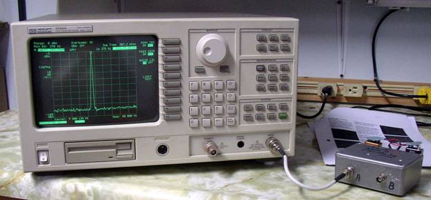
There is a GPIB connection on the back, and I have ordered a Prologix USB-GPIB adapter to allow communicating with the analyzer via a PC to allow plotting, screen captures and the use of programs to do assorted tests, like phase noise comparisons. There is a floppy drive that uses the older 720K format… I might be able to make use of that as well.
Phase Noise Measurements: This unit has impressive specifications. It’s internal noise characteristics are better than -118 dBC/Hz. The unit passed all of the self calibration tests. There are several excellent noise measurement application notes on the AGILENT website for this unit. Using an offset marker and the proper averaging of the noise floor, accurate noise measurements are easy to make. The machine reads noise in absolute values directly ( this is PSD, Power Spectral Density.. a very useful comparison number) and by using an offset marker and the built in marker noise measurement feature, you can get the traditional noise below carrier levels.
Results:
For my little test oscillators ( shown in the above photograph)
PSD of carrier: -32 dBm/ Hz
PSD of noise floor: -118.4 dBm/ Hz
Carrier level phase noise: -111.4 and -112.7 dBc/ Hz ( there are two oscillators in the unit)
Note: I arbitrarily picked a spot 16 kHz away from the CW signal for the noise floor, in all cases.
So.. as suspected, the oscillators are suitable for measuring IMDR’s in the 95 to 100 dBc/Hz range.
What about the HP 8640B’s phase noise? Well, that was job two. I lugged one of the HP8640’s over to the analyzer and tuned it to the same frequency and output levels of the test oscillators.
PSD of CW signal at 9 mHz: -46 dBm/ Hz
PSD of noise floor: -129.42 dBm/ Hz
Carrier level phase noise: -114.4 dBc/ Hz
That’s interesting. According to this number, these signal generators may in fact be perfectly fine for IMDR tests after all.
Adam Farson ( in Vancouver) has acquired a new analyzer and is also measuring his HP 8640’s to see how they compare. Adam’s numbers are to be trusted as he is very careful with his measurements and interpretations. It will be very interesting to see his results. I am going to send him a clone of my home made oscillator to compare, as well.