K9AY
Loop at VE1ZAC, Finally
Jeff VE1ZAC,
April 28,210
Yes, I
finally got around to putting up a K9AY loop. I took this in stages by playing with the Pennant loop with
Vactrol circuit first. The Vactrol worked very well.
A
word about Vactrols:
Seems very few people have anything good to say about them. Why ? There is a feeling they burnout very quickly and are
less than reliable for antenna use. I looked into several published circuits
for them and could see several problems right away. First, the resistor element
side is installed right into the loop, with the potential for static and large
local RF pulses to go through them and to the ground. They are not designed to
handle very large currents, but certainly larger than the normal currents on a
receive antenna. How to make them more reliable ?
First, do not DC couple them to the loop. Use
capacitors for AC coupling. ( Decent ones, with a few
hundred volt rating and .1 uFd) The capacitor Z is very very
small compared to the loop Z, so they will
not affect signal levels. The next thing to do is to add protection diodes
across the element. A previous article on this website looks at the affects to
the impedance of the device in RF circuits. The best diodes are fast recovery
diodes (FRD’s) of 3 amp sizing. These diodes had no affect on the RF
characteristics of the resistor element up to 14 MHz or beyond. The turn on voltage of .4 volts or so will
easily protect the element, and in fact, the circuit I have had outside on the
Pennant for 8 months has had no problems whatsoever. I control mine with a DC
signal over the coax. Incidentally,
there is a 160 M transmit vertical about 50 feet away, and I regularly use a
600 watt amp on 160 and 80M.
The K9AY control.
I intended to keep my existing Pennant control device and simply add a two
relay control line and a pair of switches on the front of the unit to select
either of the loops and to reverse whichever one is engaged.
The green
and yellow toggle switches were added for loop and direction control. This box
contains a Dallas Lankford inspired CBTF preamp (highly recommended, by me !) and a 10 turn pot for control of the current to the
Vactrol. The meter is a logging scale which allows accurate resistance
knowledge of the Vactrol. The MA label needs to be replaced..
it is really a logging scale now, not mA. I use this
scale with a chart of calibrated R values for the Vactrol which was set up on
the work bench before installation.
The
control board:
Having EagleCad and a milling machine for making
circuit boards, it’s no great trick for me to make custom boards for projects
like this. Here is the board layout and the schematic:
There
are wire jumpers between LSP1 and 2 and another between 3 and 4. I experimented
with a prototype to test out the famous “K9AY Ground” controversy, and in my
case, it works best with the antenna ground and coax ground connected. In fact,
it didn’t work worth crap when isolated. Likely this is because of the complete
lack of any real ground under this antenna. It is really loose rock with a
token soil layer on top. VR and VD
represent the Vactrol device. The 1n5400 diodes are really FRD types. And, T1
is actually a binocular 9:1 RF transformer. The two antenna loops plug into S-W
and E-N.
The pad
on the low side of the matching 9:1 transformer provides a better and more broadbanded match to the coax. You can leave this out, but it is good
practice to use it with this type of coaxial coupling. The coax shield is connected to the antenna
ground, and has three snap on chokes right at the connector. (
An F connector in this case)
Here is
the board layout viewed from the top side: (traces on bottom)

And,
here is a picture of the finished unit:
The
board was given a good spray of clear conformal coating before taking outside.
Installation:
My usual use of surplus F-18 aircraft wire for antenna and control
elements. I also installed four 15 ft radials under the loops to give a little better
ground effect. The antenna seems to work a little better with them than
without, so they stay.
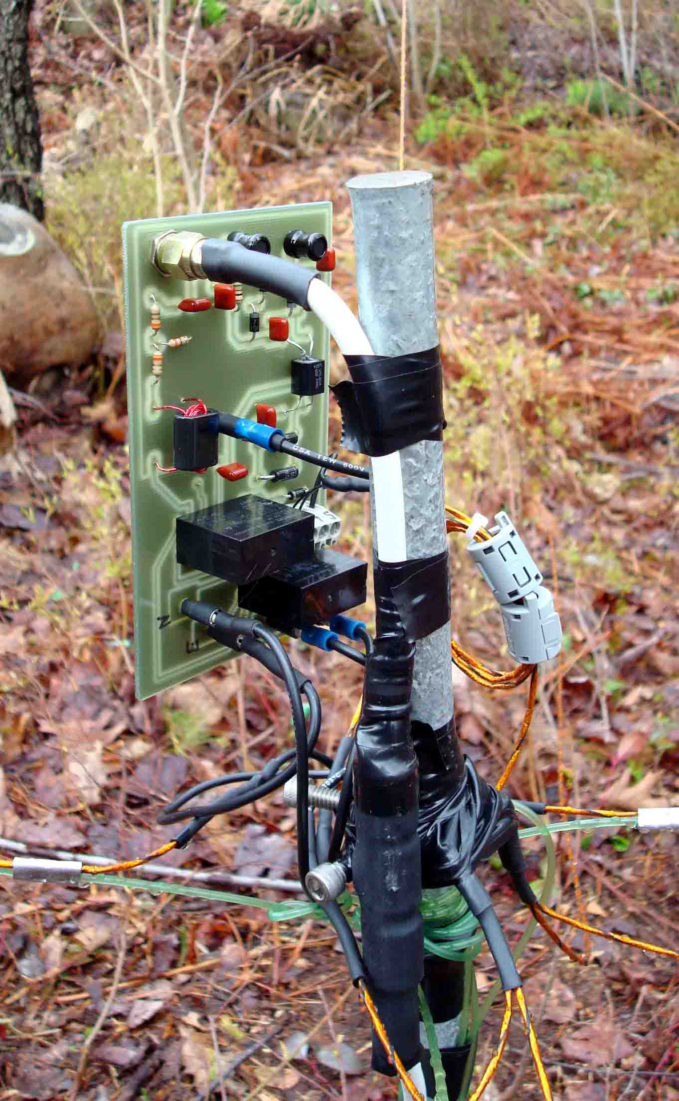
Protection
is provided by a 4” plastic pipe with cemented cap. The bottom is open. You can
see the chokes on the control and coax. My system is suspended from a tree
branch via a Kevlar halyard and door spring. The loop corners are all fixed via
a piece of shock cord.
Operation:
Here are my observations over a solid week of listening and comparing:
1)
Surprisingly
sensitive antenna, even on the high bands.
2)
I
have observed nulls of between 24 and 36 dB, in all directions.
3)
It
does need to have different termination resistors on various bands. My
observations go from 21 K ohms to 190 ohms. If I had to live with one resistor
value, I would use about 300 to 400 ohms as the optimum number.
4)
This
antenna shows least directional characteristics on 40M. Still very sensitive
though.
5)
LF
beacon band to 15M are all directional (that is, nulls will form) I am kind of
surprised how well this works on the higher bands, but work well it does.
Conclusions: If
you haven’t built one of these yet, I have to say it is a remarkably good small
space receiving antenna. I have mine parked on the
side of a slope in a wooded area with very little space to the property line,
and very close to my shack. It still works very well.
They are not hard to build. It’s nice to
have a variable resistor in the loop, but probably nt essential. It would still be a very useful antenna
without the varying element. Many of the commercial kits use a series of 3
relays and 4 resistors with a somewhat complex switching system to provide a
set of values. Works as well as the Vactrol, but more relays which can also be
a problem and lots more control wire and switch complexity. Balanced against
the Vactrol circuit.. looks
like there is no clear winner.
If you don’t want to buy a pricey unit or
build from complete scratch, there is a nice kit of parts and boards from FAR
Circuit Boards worth looking at. It is a bargain for what it ships with. You
still provide switches, power supply and whatever boxes you wish to use. Be
sure and spray conformal coating ( clear acrylic) on
ANY circuit boards you intend to leave outside like this, to prevent corrosion.
In this climate it is highly recommended that all housings have LARGE vent
holes at the low point of the case to allow the inevitable condensation to drip
out. I gave up using tight cases years ago, and now favour plastic pipe with a
cap that can be slipped over your boards, relays, matching devices, etc. All maintenance from
condensation has ceased as a result. IE, go “Drip Proof”, not total enclosed.
Good luck with your K9AY..
these are very worthwhile receiving antennas to
operate with.
Jeff Smith, VE1ZAC