‘ARDUINO UNO’ Desires
Conversation With IC-7700, For Amplifier and Tuner Control Fun
Jeff
VE1ZAC
I thought
I was making my shack and rig more
convenient and more efficient for DXing and
contesting. For unsound financial and ‘need’ reasons, a nice new solid state
amp to replace my venerable homebrew 600 watt amp seemed like the perfect
spring ham project.
The
Ameritron ALS-1300 caught my eye and I decided to give one a whirl. While I was
at it, it seemed like a perfectly good idea to order a high power auto tuner to
go with it, and an MFJ-998 joined the procession. After dealing with the
problems of ordering from MFJ’s factory supply chain, I was told by a nice lady
at Ameritron that most of their inventory is carried by dealers. It took 2
months to discover that. One day later,
DX Engineering had one shipped to me !
A nice
feature of solid state amps is the ‘no-tune’ power mosfet PA design, although
you have to load it with a pretty darned good match. So, a decent matching
device is a necessity around my shack. The 998 is an auto-tuner and advertised
as having a built in radio interface.. oh boy ! It also can control the rig
–amp key line to insure the amp is put in standby on a tuning cycle. This radio
interface, and the band switch adapter I ordered for the amp should allow
seamless interfacing with the IC-7700 or other rig I might want to hook up to
it. Right ? Wrong ! Nothing is that simple, as we all know.
Problem
number 1
The MFJ
radio interface is the well known, ultra reliable and ubiquitous AH-3/4
interface that is included with every Icom HF ham transceiver since the bronze
age. Except… the IC7700 and 7800. Some Icom marketing genius ( probably a
committee with a locked down QA process) decided that the external tuner
interface would no longer be required with these rigs. I can’t even guess what
twisted logic produced that one. But, we 7700 and 7800 owners don’t have
it … no easy remote tuner hook up for
this interface.
What is
this interface anyway? When a properly
interfaced remote tuner is plugged into the port on any other Icom HF rig.. the
rig’s software detects it and causes a new set of commands to be run when the
rig’s TUNE button is engaged. Normally, the rig goes to low power, switched to
AM, calls the remote tuner to engage, accepts a TX command from the remote
tuner, and allows the tuner to do it’s tune cycle. When that is done, the tuner
tells the transceiver to go back to receive, go back to whatever mode it was
in, and put power back where it was.
It’s actually about 6 steps. And it works beautifully.
One the
other hand, I have an interface plug and a radio with no interface. So.. how do
I join these guys ?
The DXLab Commander Solution
Dave Bernstein’s Commander (which is an integral part of my station) has a very workable method of creating macros to attach to custom push buttons in the Commander window. I spent quite a bit of time working with this and pestering Dave into helping out. As usual, he sends along the relevant info when you need it. I hope he finds this entertaining. I would probably find it irritating. I started out with the belief that I could deal with the tuners need to control the TX process. The only hope was to use the LPT port which can work with some Commander macro commands. But after spending many hours fooling with this I had to give it up. One problem was the laptop I use for a station computer. Like most laptops today, there is no LPT port. And the USB-LPT adapters for printers do not allow “Bit-banging” the data lines that you can do with an old fashioned embedded LPT port. I did find a PCIexpress card LPT adapter that did work after a fashion, but you couldn’t control a bit well enough for the tuner needs. I abandoned that idea. I did, however, create a couple of little macros that would do the job and work with the tuner without the radio interface. But you have to be careful to take the amp offline first.
I made
4 macros:
1) Set
the rig up for amplifier use. Low power, CW, Ant4 ( which is where I drive the
amp), turn auto tuner off, turn tuner start off.
2) Do
all of 1) and do a timed AM, low power
TX.
3) Do all of 2), but deal with a split VFO mode.
In this case, I swap VFO’s, turn split off, do the tune, and put it back.
4) Revert
rig back to regular ( non amp) CW mode.
NOTE:
I only use CW, so I didn’t bother with any SSB interaction, but one could
easily do that.
This worked pretty well, but you have to be careful. However, I still wanted the full auto deal and looked for another solution. Actually, it’s one I had in the wings anyway.
Yup,
it’s time for an Arduino to hook-up with an Icom !
The
ARDUINO Solution
If you
don’t know what this is, GOOGLE it, and be amazed. This is the hottest little development
board around and is perfect for gazillions of amateur radio projects. And dead
easy to use. And cheap! The programming environment is open source and java
based and runs on anything. There are hundreds of websites and learning
opportunities on line, so I won’t re-invent the wheel here. I have used them
for a couple of other projects and for a couple of work related projects and
find they are everything advertised, and more. The basic board has everything
you need on board including 14 digital I/O pins, a hardwired serial port,
programmable serial ports if you need them, 6 A/D I/O ports… etc, etc. It self powers from USB port to your computer, and when done, you
just plug it into whatever DC source over 5Volts you have around. It boots on
power up. And anytime you want, you just plug a USB cable back in for tweaking
code, monitoring things, etc.
The Arduino homepage: http://www.arduino.cc/
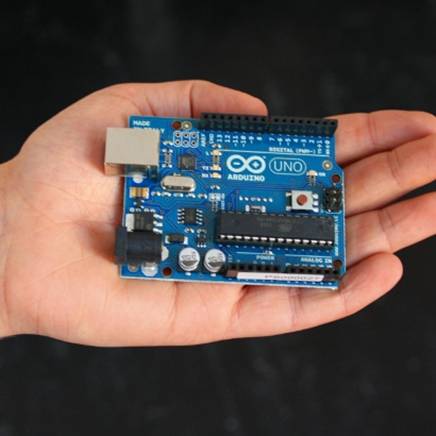
This is the popular ‘UNO’. It can store 32K
of program and data in it’s EEPROM.
They
run around $30, and can be had from many
sources. I like SparkFun Electronics and CanaKits for Arduino supplies. If you get one to play with,
it is a really good idea to get at least one of the little experimenters
‘Shields’ that plug into the top of the board and allow quick experimenting.
(You will see one in my setup a little further along.)
Writing
Code: Caveat
Emptor.. I am not a professional coder. I can do what I need to do and have
written code in various languages and platforms for the last 35 years, but ‘I ain’t no expert’. I am sure almost anybody could do this
better than me. But, I have included the project code at the end, if you want
to wander through it. Arduino language is almost like C++.
Some
requirements for the code:
- Receive data and transmit Icom commands from/to the
IC7700 via the CI-V serial buss line, at 19200 baud. (√…. Means this
is done)
- Transmit whatever Icom command is needed from a
command table in the code. (√)
- Test the rig for split
VFO’s (√)
- Work with the tuner to
start the tune cycle and receive and forward the 998 tuner TX command to
the IC-7700 as needed. (√)
- Auto setup the rig to work
with the amp as required. (√)
- Wait for a Tune cycle call
from a manual pushbutton located near the tuner. (√)
- Provide a little panel
feedback through a red and green LED. (√)
- Allow easy access for
software tweaks and changes (√)
- Provide a delayed power up
function on the tuner interface line, to simulate a real radio being
attached. (√)
- Power from the amp/tuner
combo. ( more
on this in text)
(√)
- Organize auto band changes
to the amp from the IC700 (not done yet, more in text)
- Operate reliably (!) ( probably not there
yet, although it does work. There are a few odd occurrences with the tuner
occasionally, that need some tweaking, nothing that is dangerous though.)
OK, I
got through the requirements list and used about 15% of the space in the
EEPROM. You can look at the code at the
end, if you are adventurous. I have some half baked comments in the code, but
they need updating as well. You will see a lot of rem’d (// prefix) lines
involving printing. These allow important variable to be displayed on the
Arduino serial port monitor when you have a computer hooked up, and are for
debugging. They aren’t need for normal operation, so they are turned into
comments.
Sending
commands to the IC-7700 is straightforward. Reading data from the rig is the
trickier operation.
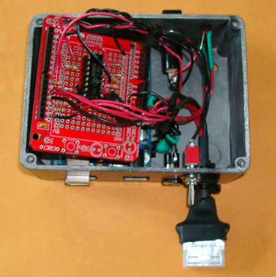
Hardware
I put everything
in a small die cast box that allowed two cover screws on the amp to be used to
hold it in place. I also tapped into the 12 volt DC supply in the amp to
provide external 1 amp PTC fused power for the tuner and for this device. It
all comes alive when you turn the amp on. Amp is ready to roll in about 8
seconds.. pretty cool for a fast QRO when needed.
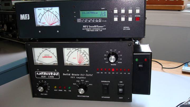
I only had a black push button in the shop.. an unfortunate choice for photographing. It will look better with a label. The box on the right houses the device. Too bad MFJ and Ameritron didn’t select a common width for these two products.. they would stack a lot better. I suspect they are often used together. I put some extra stick on feet on the tuner so it sits on top fine.

Looks kind of like an InookChook, don’t you think ?
The
ARDUINO – CIV circuit
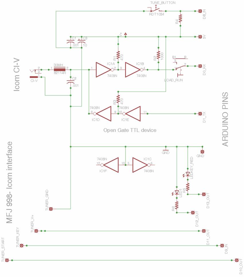
This
needed a bit of thinking. The Arduino is a 5 volt supply circuit. And the
serial pins are also 5V+ to 0 V levels. The CI-V interface should be fairly
straightforward and I discovered an article where an open gate buffer was used
for this purpose. I didn’t have any TTL or LS devices around like that, but did
have a SN7405N which is a hex inverter with open gates. This should work fine,
but you need two inverters in series to get a buffer with no inversion function. No problem. Open
gates require a pull up resistor. Unfortunately the 1 K resistor I used on the
gate output going to the Arduino also caused some USB problems. The Arduino
shares the USB port on the ATMega386 processor chip with a USB FTDI chip. The
1K resistor pulled the port too high for USB downloads. No problem, I added a
switch in the line which is only needed when you download new code. Normally it
is left closed. SN7407 and SN7417 are open gate buffers, or you could use
pretty much any LS or other variant of these things.
I also
paid a lot of attention to RF filtering on everything going in and out of the
box. So far, no RF feedback problems. Here are some construction pictures and
the schematic of the interface:
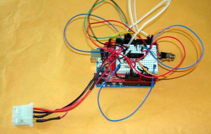
The Arduino with a Spark Fun experimenter
shield
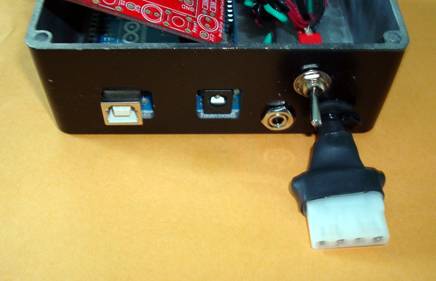
The back with the interconnections. The molex connector is a surplus computer power connector
modified to look like the Icom AH-3 plug.
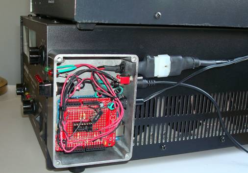
On the side of the rig.
The schematic:
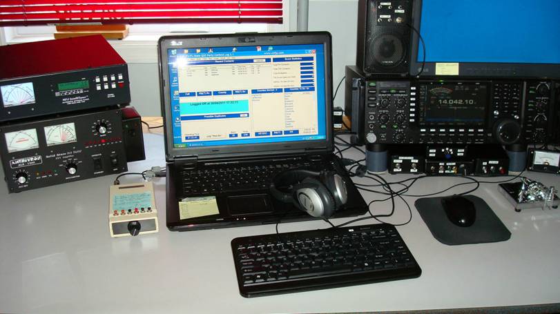
And,
the operating position with everything buttoned up
What’s
left?
The
auto band switching.. that’s what. The amp came with a little interface that
actually does decode the IC band data from an auxiliary connector on the back
of the rig. Problem is… it disables the amp standby switch for some reason. I
was pretty disappointed with that. I think it is essential to have that switch.
I notice Phil Silas has a mod for that on his web site and that might be the
solution. Or, I could add code to the Arduino to read the band switch and
control the amp. Both can be done. I will probably try the amp interface
modification first, and if that doesn’t work out, then go to the Arduino code.
The
code: Here it is.. read it and weep !
If you
decide you want to play with this, email me and I will send you the file. Or I
might post it in the file section for either the IC7700 Yahoo group or the DXLab Yahoo group if Dave Bernstein thinks it is OK to do
that. If you are the code type but don’t have experience with the Arduino, have
a quick look at the website for the Arduino wiki reference.. it gives a basic
overview of what’s going on.
//the AH-4 tuner function for Icom CI-V and MFJ 998 control
//commands work with Icom
interface enabled in 998 tuner
//and Icom
CI-V line with Arduino processor
//reads key line from tuner
//controls start line and radio Tx and Rx
//
// define the pins we need for
interfacing
//LED is to show STARTTUNE running
// Use a delay when turning split on and
off before proceeding as rig
//is slow to respond
#define TUNEBUTTON 8/ / the PB on unit to start process
#define LEDKEY 13/ / LED pin,
#define LEDTUNE 12/ / LED pin,
#define KEY 9/ / t u n e r t x switch, normally high
off
#define TUNESTART 10/ / S tart on tuner cable, normally high
off
#define TUNEPOWER 11/ / delayed response to simulate radio
;
// These are all the command arrays
needed
//array elements are DEC versions of HEX
command
// add more as needed and transmit in
byte array loop
int tx[8] = {254,254,110,224,28,00,01,253}; // turn tx on
int rx[8] = {254,254,110,224,28,00,00,253}; //goto receive
int dis[8] = {254,254,110,224,28,01,00,253};/ / disable tuner
int toff[10] = {254,254,110,224,26,5,0,113,0,253}; // disable tuner auto
int lp[9] = {254,254,110,224,20,10,0,101,253}; // set rig to low power
int amlp[9] = {254,254,110,224,20,10,0,144,253};// set at 80 for AM
int am[7] = {254,254,110,224,6,2,253};/ / AM mode
int cw[7] ={254,254,110,224,6,3,253};/ / CW mode
int ant4[7] ={254,254,110,224,18,3,253};/ / use ant 4 position for amp
int hp[9] = {254,254,110,224,20,10,2,85,253}; //back to high power
int tun[8] ={254,254,110,224,28,1,1,253};/ / e n able tuner
int ton[10] = {254,254,110,224,26,5,0,113,1,253};/ / e n able tuner auto
int splitoff[7] = {254,254,110,224,15,00,253};
int spliton[7]= {254,254,110,224,15,01,253};
int swapab[7]={254,254,110,224,07,176,253};/ / swap VFO A and B
int split;// split
indicator, 1 or 0
int splitmarker;
int buffcall[6] = {254,254,110,224,15,253};/ / command 0F buffer
int buffget[7] ; // the receive buffer
// some control variables
int i;
int incoming;
int value;
int value2;
int valuekey;
int old_value = 0;
// This loop run once on start up to set
up things
void setup() {
Serial.begin(19200);
pinMode (TUNEBUTTON, INPUT);
pinMode (KEY,INPUT);
pinMode (LEDKEY, OUTPUT);
pinMode (LEDTUNE, OUTPUT);
pinMode (TUNESTART,OUTPUT);
pinMode (TUNEPOWER, OUTPUT);
digitalWrite(TUNEPOWER,LOW); // delay showing +V line on tuner for 5
seconds
delay(8000);
digitalWrite(TUNEPOWER,HIGH);
digitalWrite(TUNESTART, HIGH); // be sure TUNESTART pin is high
digitalWrite(LEDKEY, LOW);
digitalWrite(LEDTUNE, LOW);
}
// MAIN
void loop() {
//start the split detector here
listen:
delay(100);
for (i=0; i<6; i++) {
Serial.print(buffcall[i],BYTE); //send command to ask for split,
0F
}
//delay(5); // give a delay from radio
to respond
next:
if (Serial.available() >0) {
incoming = Serial.read();
if (incoming == 254) {/ / 1st
byte is an FE look for an FE to start
goto start; }
goto next; }
start:
//Serial.println("
");
delay(2);
for ( i=0;i<6;i++) {/ / g et next 6 bytes
if(Serial.available() >0) {
buffget[i]=Serial.read(); // load buffget
with next 6 characters
delay(2);} //delay 2 ms if true.time for buffer fill
} / / OK, got new 6 byte buffget array
if (buffget[3] == 15){ // check to see if 4th char is 15
goto next1; }/ / 0 F detected , go to next1
goto listen;/ / wrong array, get another
next1:
delay(2);
//Serial.print
(" split present = "); // We have an array
// Serial.print(buffget[3]); // print the 0F , or 15 to be sure
if(buffget[5] == 253 ){ //look for an FD at end of array
goto maybe; } // if fd detected, goto maybe
goto listen;/ / wrong command
maybe:
delay(2);
//Serial.print("
maybe split= "); //have an array that should have a 15 in it
//Serial.print(buffget[4]); // print the split data
if(buffget[4]== 0) {
split=buffget[4];
goto finish; }
if (buffget[4] == 1) {
split=buffget[4];
goto finish;}
goto next;/ / not valid split status.. go again
finish:
delay(10);
//Serial.print("
finish = ");
//for( i=0;i<6;
i++) { // buffer will be missing first FE
//Serial.print(buffget[i],DEC); // print out
entire buffer
//Serial.print("
"); }
Serial.println(" ");
Serial.print("
Serial.println(split,DEC);
// now wait for tune button
wait:
//digitalWrite(TUNESTART,
HIGH);
i=0;
wait5:
value = digitalRead(TUNEBUTTON);
i=i+1;
if ((value ==HIGH) && (old_value
==L OW)) {/ / wait for TUNEBUTTON to push
delay(10);
if(i > 1000){/ / if nothing happens in 1 sec, check split again
goto listen; }
goto wait5 ;
}
old_value = value;
//Serial.println("
start button pushed");
// decide on what to do about split
if(split == 0) {
splitmarker = 0; //no split, carry on
goto vfogo;}/ / s p lit must be off
// split must be on, turn off
// first, swap VFO's
splitmarker = 1; // use this marker to keep tabs on what the split should be
for( i=0; i<7; i++){/ / s wap VFO's
Serial.print(swapab[i],BYTE); }
for( i=0; i<7; i++){/ / t urn
split off for tune routine
Serial.print(splitoff[i],BYTE); }
delay(100); // takes a
while for the radio to execute split
// beggiining
of the vfo routine
vfogo:
for( i=0; i<8; i++) {
Serial.print (dis[i],BYTE); } //disable tuner
delay(2);
for(int i=0; i<10; i++) {
Serial.print (toff[i],BYTE); }/ / d isable auto tuner feature
delay(2);
for(i=0; i<7; i++) {
Serial.print (ant4[i],BYTE); }/ / a nt
4 select
delay(2);
for(i=0; i<7; i++) {
Serial.print (am[i],BYTE); }/ / A M mode
delay(2);
for(i=0; i<9; i++) {
Serial.print (amlp[i],BYTE); }/ / AM LP
delay(2);
digitalWrite (TUNESTART,LOW); // start the tuner cycle, take TUNESTART pi
digitalWrite (LEDTUNE, HIGH); // Turn on LED during tune cycle
//Serial.println("
tuner started");
delay(400);
digitalWrite (TUNESTART,HIGH); // stop the tuner cycle, take TUNESTART pi
delay(5);
keyon:
valuekey = digitalRead(KEY);
if (valuekey == HIGH) {
goto keyon;
}/ / w a i t f o r t u n e r t o s t a rt
//start transmission
//Serial.println("tuner
says start");
digitalWrite(LEDKEY, HIGH); //Flash the KEY LED
for(i=0; i<8; i++) {
Serial.print (tx[i],BYTE); } //transmit on
keyoff:
value2 = digitalRead(KEY); // wait for cycle to finish
if (value2 == LOW) {
goto keyoff; }
//Serial.println("OK
done");
digitalWrite(LEDKEY, LOW); //turn KEY LED off
for( i=0; i<8; i++) {
Serial.print (rx[i],BYTE); } //transmit OFF
delay(2);
for(i=0; i<7; i++) {
Serial.print (cw[i],BYTE); } //back to CW
delay(2);
for(i=0; i<9; i++) {
Serial.print (lp[i],BYTE); } //lp power
//Serial.println("...
cycle complete");
//check split marker
if(splitmarker == 0){
goto done; }
for(i=0;i<7;i++) {
Serial.print(spliton[i],BYTE); } // put split back in place
delay(100);
// swap VFO's back
for( i=0; i<7; i++){/ / s wap VFO's
Serial.print(swapab[i],BYTE); }
delay(2);
// Turn off TUNE LED
done:
digitalWrite (LEDTUNE, LOW);
split = 0;
splitmarker=0;
goto listen;
}