An LF UpConverter to play with a K9AY antenna
Jeff VE1ZAC May/2010 (Updated Dec 26.2011)
In a relapse of one of my occasional bouts of interest in seeing just what is still being broadcast on various parts of the HF spectrum, I have been exploring just how useful a small terminated loop, like the K9AY can be. Turns out, it is a remarkably good low band antenna, as many have reported. There are excellent BCB AM catches to be made with it, as you have the ability to null reception in the opposite direction by 24 to 30 dB. This can make all the difference in listening to AM BCB stations in the UK and Europe at night, with their 9 kHz spacing ( compared to the 10 kHz spacing used in NA) There are many open frequencies allowing decent reception of some of these stations. I can hear 12 to 15 of them some nights on the K9AY. The other antennas here, like the windom OCF dipole and the vertical are not nearly as good… to the point of being “Deaf” in some cases. The phase controlled short SWA I have at this site can create better nulls, but sensitivity is better on the K9AY. A further experiment, at some point will involve erecting a second K9AY and using two of them as an array. Maybe later in the year. ( New: I have since added a phase controlled pair of small 10 foot whips with Dallas Lankford inspired low noise techniques, twinlead feedlines, 'superchargers',etc., that far outperform any other antenna here on LF, below the broadcast band, including the K9AY)
However, below the BCB, there are things to listen to. In tuning down in that area I can hear broadcast stations in the 150 to 250 kHz area on the K9AY that I cannot hear at all on my other antennas. Amazing. Very directive on the K9AY too. Although, the output is very low, at night there is enough signal without a preamp, with my Icom 7700. However, the preamp on my K9AY is a superb Dallas Lankford inspired common base transformer feedback ( CBTF) job of 12 dB gain. This is , without a doubt, the best RF preamp known to mankind. ( Lots of info in other articles on this site.) A preamp of some sort will likely be needed with an upconverter.
Some of my friends with decent receivers don’t have capability in the area below 500 kHz, so I thought it would be fun to whip together a little up converter to use with the K9AY to allow reception of LF signals and move them upband. In my case, I put them all at 4 mHz and up. Thus, an upconverter circuit is needed.
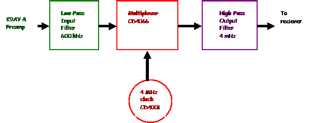
There are several ways to do this. The conventional way is to use a heterodyne converter stage. The other way is to use a sampling multiplexer on the lower frequency signal, with a higher frequency driven clock rate. I found a nice circuit from SM6LKM which used a 4 MHz sampling clock and a CMOS 74VC4053 multiplexor chip. SM6LKM claims the 4053 device had a better ‘On”resistance than a conventional 4000 series CMOS device. Possibly so, but not by much and like many other experimenters, my junk box is full of 4000 series CMOS devices. I found 4052’s which are similar, but even better, I found a handful of 4066 CMOS switches. These are SPST devices, 4 on a chip. The device needs a pair of low resistance switches to sample the LF signal on the high and low phase of the clock. A 4066 could be used by wiring it as 2 pairs of switches. These devices have ‘ON’ resistances that are influenced by the chips supply voltage. During experiments I found the 5 volt resistance was markedly improved when the supply voltage was increased to 8 volts, so a 9 volt battery became the convenient supply voltage. This device draws only a tiny amount of current and a battery will last quite a while.
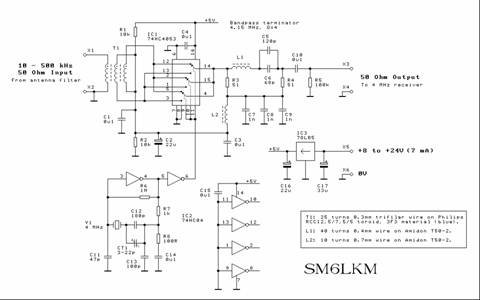
Here is the device and circuit built by SM6LKM.
The next item was to build the SM6LKM circuit, which I did. I had some 4 MHz microprocessor clock crystals to use with the inverter oscillator circuit. This circuit does not need to be an inverter. In fact any gate format can be used to implement an inverter. Two are used to make the clock work and one is used to invert the clock signal to run the second switch. I had 4001’s galore.. these are quad 2 input NAND gates. An excellent substitute.
I didn’t have a lot of luck with this circuit. It was quite deaf. I found I needed to put pretty big signals into the device to get an output. After tinkering, I found the output filter and load a little fussy. I replaced it with a simple 3 pole HP filter that would transmit everything around 4 MHz and up, and cut off anything below. My first attempt with a proper output filter worked very well, except for the little annoying feature of translating everything it was hearing from 50 KHz and up and repeating the signals above and below every multiple of 1 MHz ! What a zoo. This was with the K9AY input right to the trifilar sampling transformer. What was needed was a LP filter for the input. I added a 5 pole device which cutoff around 700 KHz. That solved the problem.
An excellent free filter application is the AADE one available on the AADE site. http://www.aade.com/ The LC meter from this outfit is an excellent shop tool BTW. I wouldn’t be without one. ( my apologies for the poor graphics)
Here is my circuit:
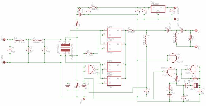
L3,L4, C6,C5 and C7 are the input low pass filter
L2,C8 and L1 are the output HP filter
The input transformer is not the correct symbol.. it’s just used for the hole layout. The actual input is a trifilar transformer as per SM6LKM’s description.
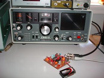
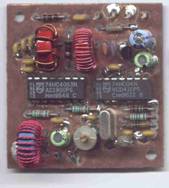
And a picture of the experimental board I made;
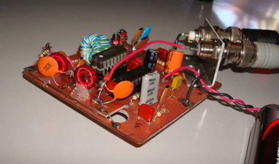
Half milled two sided copper clad board, and half “Dead Bug”. Thank heavens for glue guns.
In fact, this circuit lends itself perfectly to “Dead Bug” or “Ugly” style construction. There is nothing fussy about it at these low frequencies.
Now, in studying this picture, an observant person may notice the unusual height of the left hand chip. That is TWO CD4066’s, one stacked on top of the other, with the pins touch soldered together. What the heck is that all about ? Well, I got the “On” resistance of one pair chip switches down to about 50 ohms. By adding a second whole IC in parallel, the new “On” resistance of each switch pair is about 25 ohms. It makes a noticeable difference in operation, and it is quite funny how effective that turned out to be. A simple application of Ohms Law.
Testing before going to the radio and antenna involved inputing signals in the LF range and watching the output on the HP3589 network analyzer. My HP8640B RF oscillators don’t go down that low, but I do have an old HP861 oscillator in the shop that goes from 1 kHz to 9 MHz. 150 kHz signals are easy. Using a capacitor between the instruments attenuator and the input filter produced a perfectly adequate test signal. And, sure enough, the output has a signal right on 4.150 MHz. Excellent. Sweeping this signal around tests the input LP filter and the output HP filter. The only real problem is the lossiness of the device. There are at least 10 dB of throughput loss. That’s not a problem so long as some external gain is used with the device. The best setup is to have a preamp between the antenna and the converter, but many receivers have enough preamp gain for the output.
In my cases, I found the thing worked best with the 12 db CBTF preamp I use with the K9AY engaged.
A comparison test involved the converter hooked up to a FRG7 receiver that is in excellent condition and the IC7700 which can receive signal in the LF range directly. I could hear everything that the IC7700 could hear with the K9AY with the converter and FRG7, and in some cases, with better results. ( These are AM signals, after all)
A fun project which really highlights the low band capabilities of the K9AY or other terminated loop.