A Quick and Dirty 6M array
Accepting a challenge from VO1NO to get on 6M
and participate in the fun of 6M propagation, and wanting to try out a new ICOM
706 all-mode-everything radio, I needed an antenna that could be put together
and thrown up quickly, yet provide gain. Everybody I know on 6 M felt a beam of
some sort was essential. Along with that comes a tower. Certainly a horizontal
antenna is a big advantage on 6 M.
I am known as somewhat of a wire antenna guy, (largely self
imposed from neighbour appeasement policies)
so the challenge was on to produce an everyman simple antenna. Hmmm… well, lets add the feature that it would be nice to operate
on 2 M and 70 cm with this antenna, as well.
How to tackle the project ?
The criteria included:
· Wire antenna
· Must have gain approaching a small yagi
· Simple to make from junk box materials
Modeling
Firing up my trusty copy of EZNEC modeler, I
started with a simple dipole. From here on, I used this gain as the reference,
so all gain claims are referenced to a dipole, thus dBd.
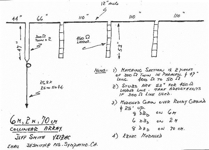
For an element made from 12 AWG wire ( insulated
electrical wire) an element length of 110 inches looks good on the model. Also,
it allows use on 2M and 70 cm. You can feed this in the center as a dipole, but
there is almost no way to avoid having a reactive feed point..
meaning that it would be really difficult to get a
good match to coax here. Plus, the reactance would be very height sensitive.
Probing around with the model, however, shows a purely resistive point at 40 %
from one end. ( 44 inches). This point also stayed
nicely resistive through a far wider range of heights, and also at the other
two bands of 2 M and 70 cm. Incidentally, the design
frequency used was 50.1 mHz. Notice that our dipole
is now an OCF, or Off Center Fed dipole.
To skip a step, array elements were added, and then I came back and adjusted
the feed point. This feed point impedance shows on the model as 400 ohms R and
0 ohms X… not bad !
To get gain, we need more radiating elements. Radiating elements in line are a
form of gain antenna known as a "Collinear Array". By adding extra
wire to this antenna in such a way that the wire will radiate our transmitted
signal in phase multiples of 360 degrees, we can make a gain array. I added 3
more ¼ wave sections and 3 delay stubs. In other words, the stubs provide a
delay so that the wire looks like another set of dipoles, each with a delayed
signal on it. We want to have all of our wire elements with a current phase of
the signal on it at the same time. We wind up with 4 elements, with each
adjacent element having a phase that is 180 degrees delayed from it's
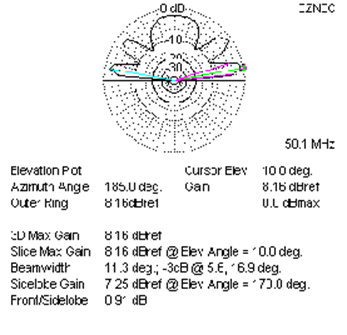
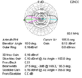
neighbour. In practice, these three elements should really all be tuned specifically to get the right delay, but by doing so, you would only get a theoretical gain increase of ½ dB… to heck with that ! This was supposed to be a simple project ! The three identical elements I have shown added 8 dB to the dipole, or a gain of 8 dBd. Even better, the pattern has nifty lobes that are fairly low take off angle. Here are a couple of views of the modeled radiation patterns in the far field.
These models are
for the antenna at 25 feet high, above a rocky ground. The lobes are pointing
off the broadside of the antenna, as you would expect from a dipole. The Ref
gain is about 4.7 dBi, which is easier to show simply
as referenced to a dipole. In effect, this antenna will put out an ERP that is
8 dB better than a dipole. How much is that ? Well, if
you can deliver 50 watts to the antenna, the ERP (Effective Radiated Power)
broadside to the antenna, and at 10 deg. elevation would be over 300 watts ! Incidentally, EZNEC allows you to view the currents
on these elements and see exactly what is happening.
Feedpoint matching
The next step is to figure out how to couple to this
antenna with a hunk of coax. The model predicted a 400 ohm resistive feed
point. What I need then, is a 400 ohm to 50 ohm transformer to hang up at the
feed point. A 8:1 broadband transmission line
transformer is a possibility, but you need pretty good core material for 50 mHz to keep losses down, and I also wanted to use this
thing at 2M and 70 cm. More importantly, I couldn't find anything suitable in
my junk box…
I did have a bunch of 450 ohm ladder line scraps and lots of 300 ohm TV twin
lead. Could a quarter wave transformer work ? Well, we
want to go from 400 to 50 ohms. We could do that if the quarter wave
transformer had a characteristic impedance of square root of 400 times 50. Or, the root of 20000, which is 142 ohms. Hmmm… that is
about ½ the characteristic impedance of el cheapo TV twinlead.
Two pieces of 300 ohm line, the right length, and hooked in parallel should do
the trick. Or be close enough.
Two build this transformer the length of the transformer should be exactly ¼
waves. Calculations showed that to be 59 inches, but that assumed 100% velocity
factor. Twinlead is not 100%, of course. It is rated
at between .88 and .92, but in practice I have found it is usually lower.
Having an antenna analyzer handy allowed me to make the stub exactly the right
length for 50.1 MHz. If you have or can borrow an analyzer, cut the stub a
little long, and hook it to the analyzer. Then trim it to the right length.
Otherwise, you can use these dimensions.
I would love to tell you what that length is, but the antenna is hanging up as
I write this article, and I can't remember what the heck it was. It is
somewhere between 47 and 48 inches, I think. Two pieces are paralleled to make
the transformer. A balun is important for this
antenna, so I taped the RG8X I used to connect to this transformer into 5 tight
coils of about 6 inch diameter. The whole thing is strain relieved and the
connections for all the joints on this antenna were sealed using liberal
amounts of hot melt adhesive.
Note, use the amber coloured,
high strength adhesive. I usually spray paint all connections with flat black
paint after cooling, to provide protection from UV, and improve the view.
You can test this transformer by putting a 400 ohm resistor in place of the
antenna, and looking at the base of the transformer. Mine showed 50 ohms and a
1.1 SWR. Perfect ! After attaching the coax, the end
of the coax still showed 50 ohms and 1.1 SWR ! (I
don't usually get so lucky). I also tried this at 2M and 70 cm, and the same
thing held… excellent match. 2M was SWR 1.5, and 70 cm was SWR 1.1. I checked
mine again, after the antenna was up in the air, and the match was still
excellent.
Additional
Antenna Elements
The next step is to build the phase delay stubs. These
can be 300 ohm TV lead, the length being exactly as determined for the quarter
wave transformer. Or you can use ladder line, like mine. The ladder line length
came out to 53 inches, since it has a higher VF than TV twinlead.
I used some plastic scraps to make the connection "T" at the top of
the stubs. The bottoms are shorted and left to hang as is. Hot melt and paint
everything. My antenna elements are black insulated #12 electrical wire. ( Had some in the junk box)
Fat wire has advantages in lowering the Q of the antenna. This makes it a
little more broadband than small wire sizes. The whole thing is about 37 feet
long.
How does it work ?
I have spent 3 evenings working 6 M openings
with it. I am very pleased with it ! Everybody I could
hear, I could work, and we exchanged similar reports. Most of the hams I worked
were using beams. You can draw the conclusion that this is an effective
antenna, or, that the antenna isn't important when there is a good opening.
Either way, we have something useful with this antenna, because it is so simple
to make and put up. Good for portable use too. I haven't tried this antenna
much on 2M or 70 cm yet, other than some 2M simplex. The signal reports were
good there, as well.
Some
conclusions?
· Computer modeling
really helps produce useful results for antenna projects
· Simple wire antennas can rival towers and beams
· A wire antenna can get you on 6M in an afternoon's
worth of effort, for little money.
· 6 M is a lot of fun!
If anybody tries this, I would really like to hear how you make out with it.
Jeff VE1ZAC